Especially for users from the 3D printing sector, the question often arises as to why the z-axis is not motorized / automated in the lasers. Quick answer in advance: you don’t really need it, manually it is almost faster in my experience. But since it is a nice gimmick, which is also fully supported by both the motherboard and the firmware, here is a guide on how to implement this anyway.
Required hardware
Basically, you can of course build the complete mechanics yourself and create them with the 3D printer. I had neither the leisure nor the time, so I took a finished module. One like this one: AliExpress link. In addition, I needed a motor and a clutch for the threaded rod.
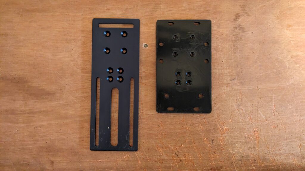
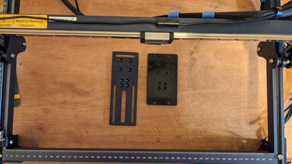
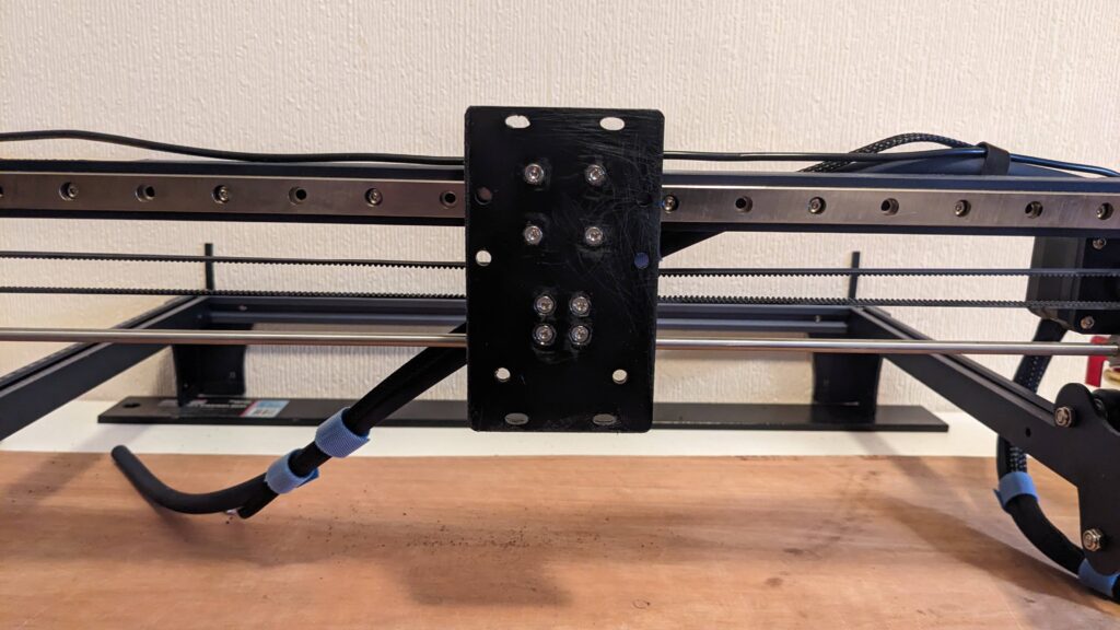
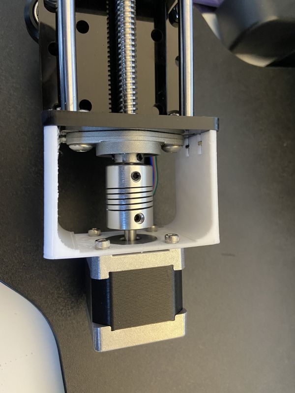
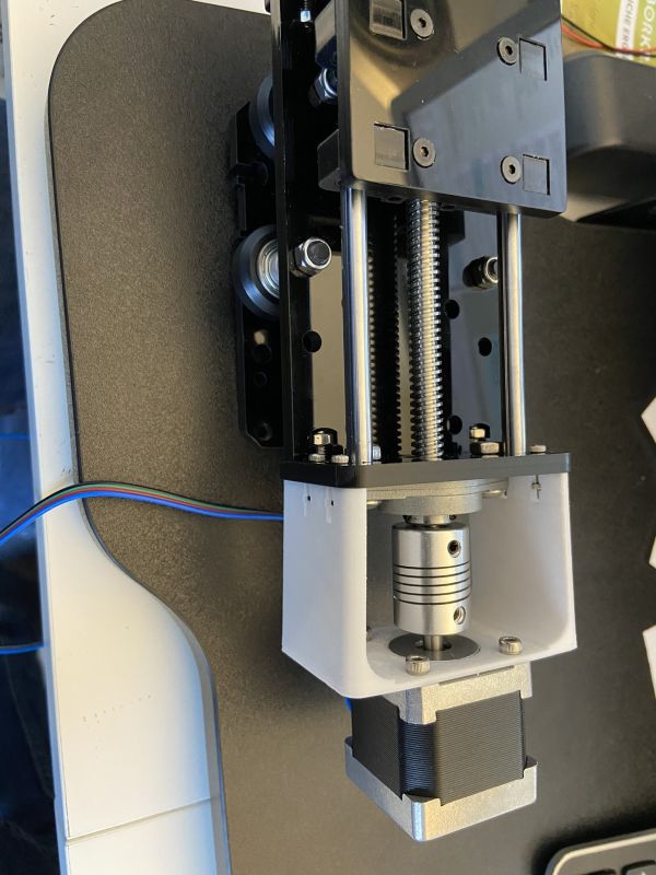
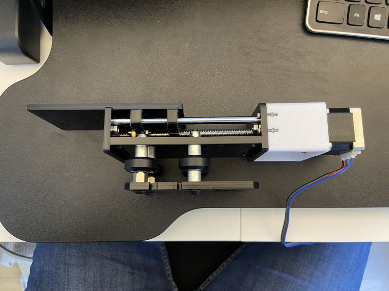
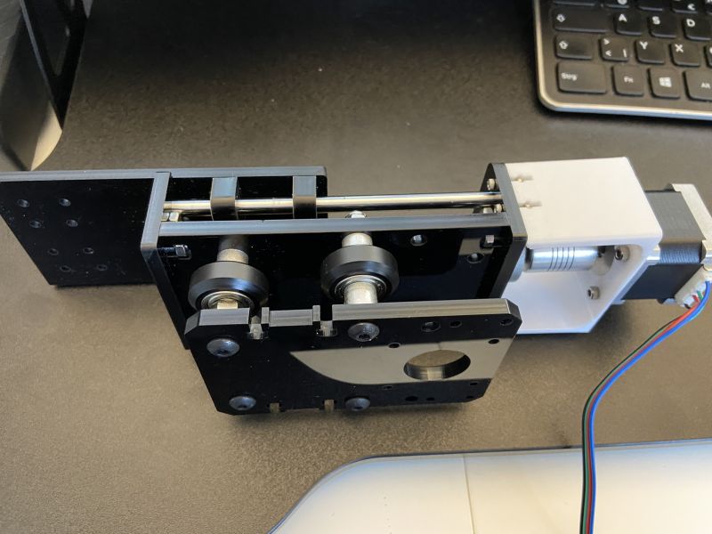
What I found very attractive about the above design was that the x-axis motor can be integrated directly and thus not too much additional weight is brought to the front of the holder of the laser module. So the weight is reasonably well balanced. The front retaining plate did not fit perfectly with the S9 module, I had to remove about 2 mm of material at the edges and drill slightly better placed holes. I used the laser for both. I drew the appropriate dimensions and then adjusted the holding module with the laser and cut out the holes.
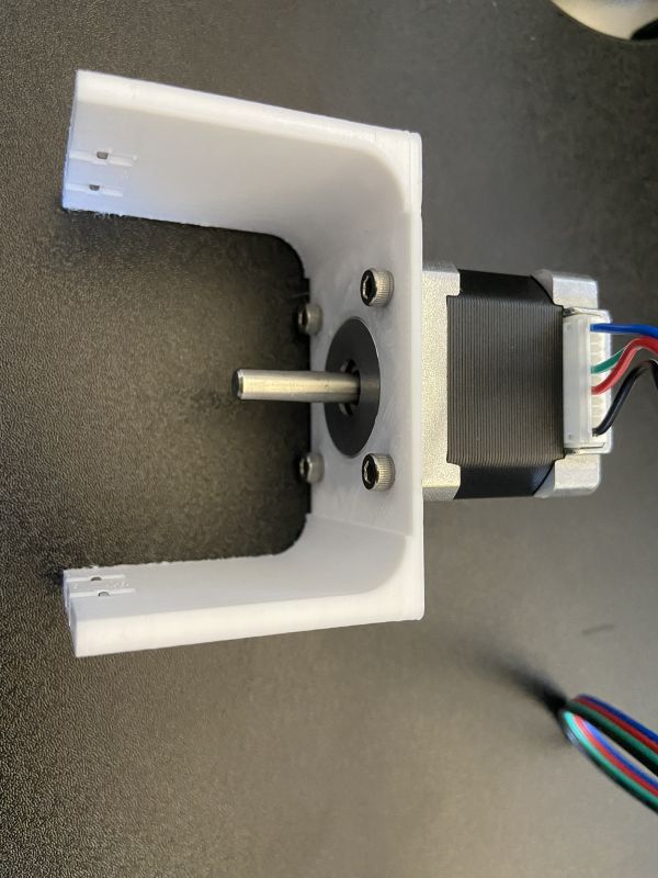
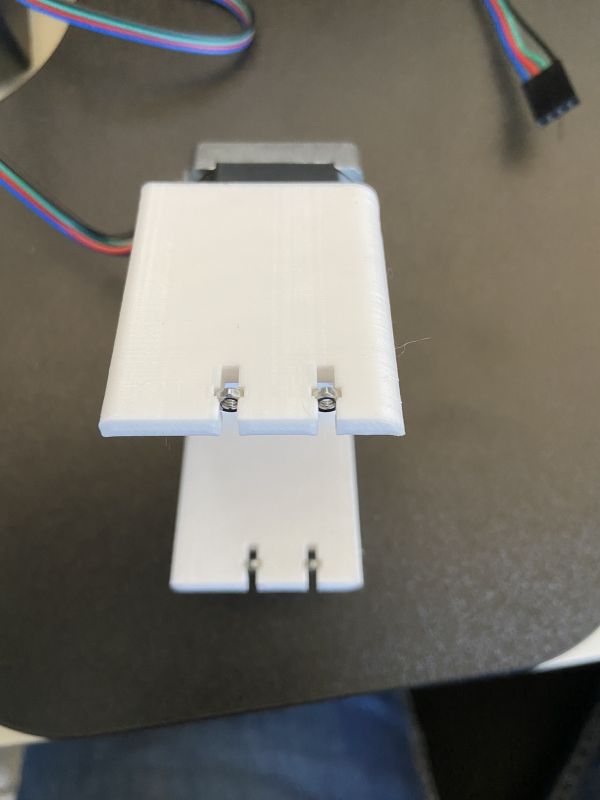
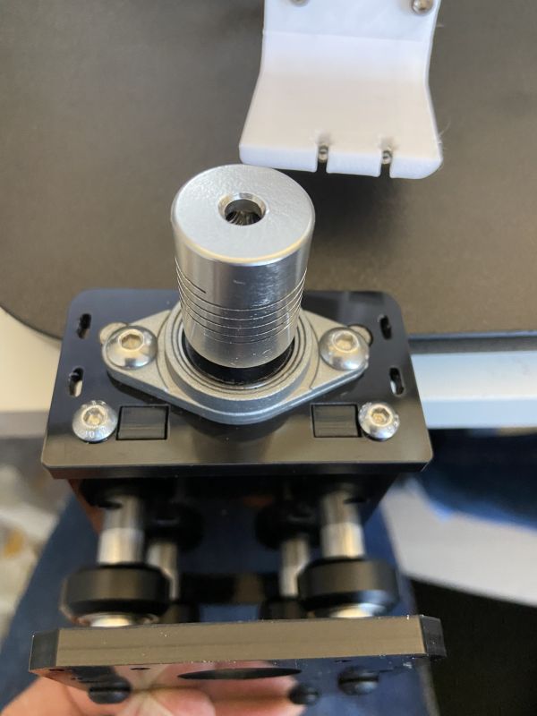
As a motor I used a Nema 14 motor (Amazon link). I wanted to save as much weight as possible there. A Nema 9 stepper was unfortunately too weak for the mechanics. I 3D printed the holder. Since I didn’t want to change much on the original bracket (drilling, etc.), it is certainly not the best in design, but it serves its purpose. To be able to connect motor and threaded rod, I still needed a shaft coupling with 5 mm and 8 mm openings (AliExpress-Link). To operate the motor parallel to the other two axes, you still need a stepper motor driver module (I took an A4988 module ).
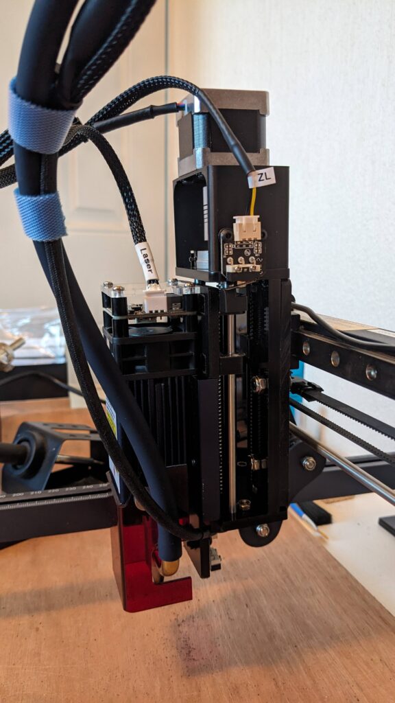
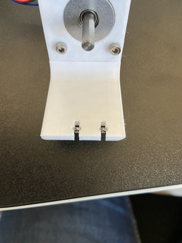
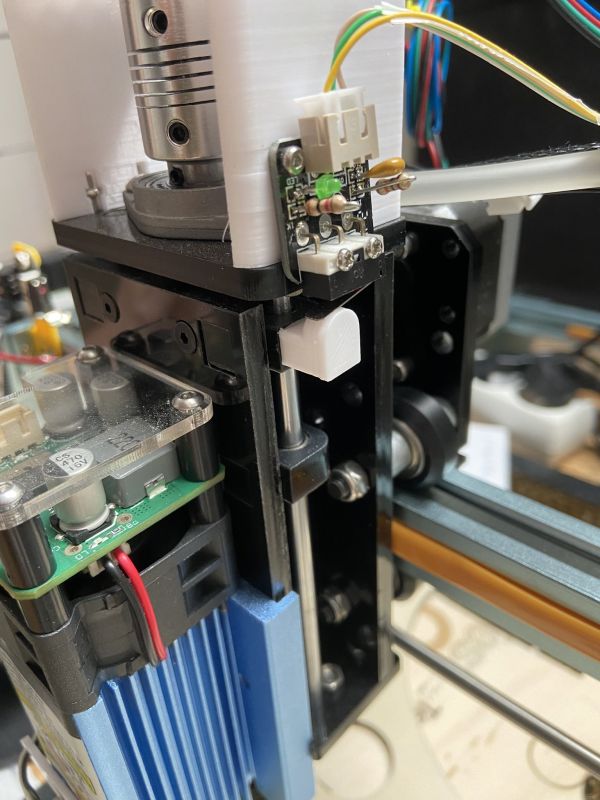
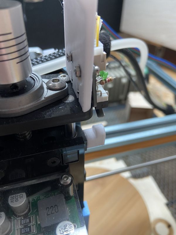
In order to have a reference point for the height adjustment, a limit switch was attached to the upper end of the z-axis. I intentionally took the upper end because from my perspective it makes sense to reference upwards, i.e., away from the workpiece. Otherwise, you could only perform a homing when the workspace is empty. Thus, the laser is always driven out of the way before the other axes are referenced. At the bottom end, I do not need a limit switch because I have measured the travel and stored it in the firmware so that the laser can never extend beyond the maximum (soft limits activated).
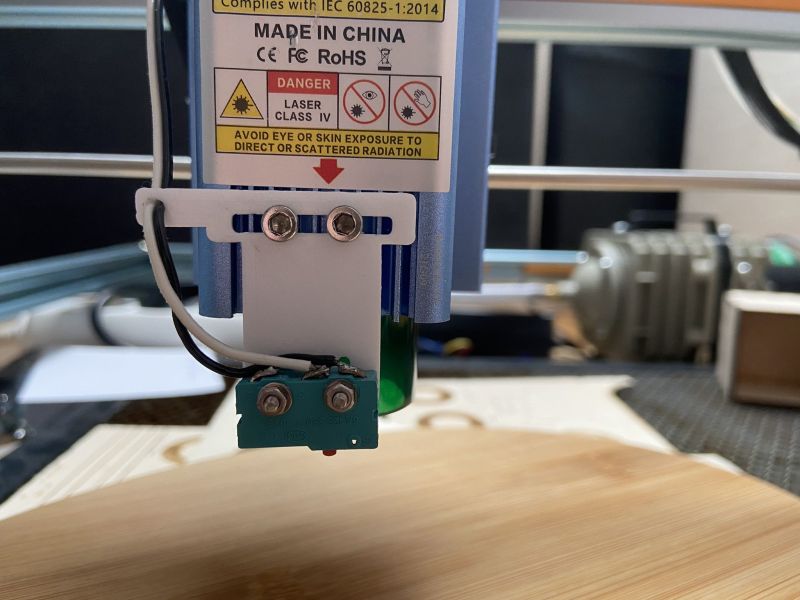
Finally, you need a sensor to feel the workpiece surface. For this, I used another limit switch and removed the metal bracket, so that only the small button remains. This sensor (“probe”) is used to stop when the material is reached.
Which mechanics are used exactly does not matter in the end. Only the following are important:
- Stepper motor for driving the z-axis
- Limit switch for referencing the z-axis upwards
- Limit switch / button as “probe” for palpating the surface downwards
The parts I created with the 3D printer can be downloaded here .
Connecting the hardware
The connection should be simple. Three ports are required on the motherboard:
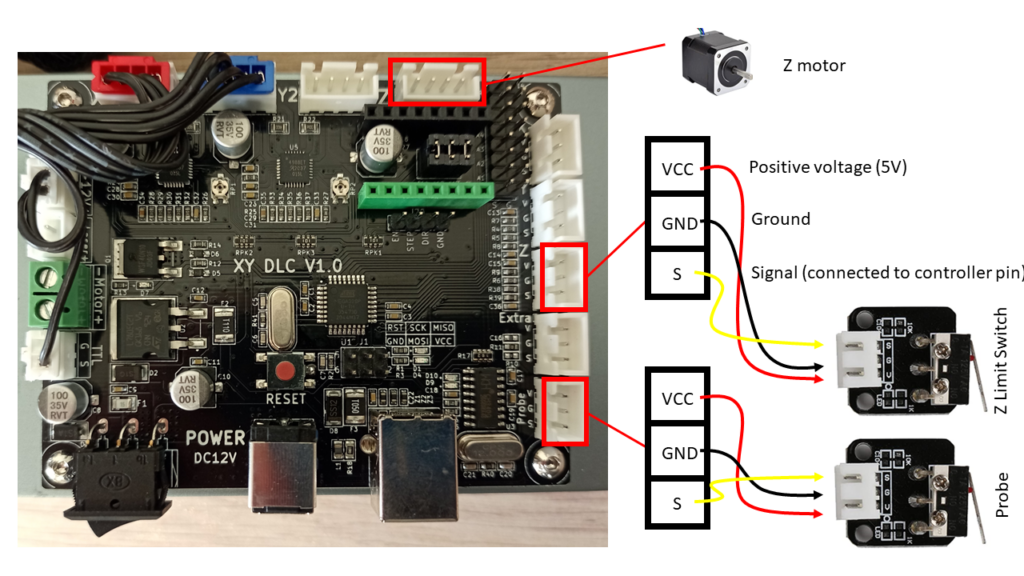
In my case, I only took a simple switch for the probe, without a debounce circuit as in the figure because it was easier to assemble. For such a switch, only two pins need to be connected: C to GND and NO to S. (C, NO (normally open) and NC (normally closed) are usually directly on the switch above the pins). The signal input on the board is typically pulled to 5V by a pull-up resistor and must be pulled to ground through the switch.
Control
The control is relatively self-explanatory in itself, as it does not work differently than with the other axes. The only special thing is the automatic touching of the surface.
Firmware
The firmware must allow homing of the z-axis. If my firmware (see this article) is used, this is already built-in. Otherwise, an update usually has to be carried out. My firmware is set so that the z-axis is not automatically homed (otherwise the procedure without z-axis would always fail), but you can start it manually. This happens with the command “$HZ” (“$H” stands for homing and if you want to home a single axis, you can attach its letter).
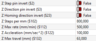
Before that, however, you should check all other settings: since it is (in my case) a different motor and of course a different translation of the movement via the spindle, the parameters must be set accordingly. In particular, these are:
- $3 = Direction port invert
- $23 = Homing direction invert
- $102 = steps / mm (steps per millimeter)
- $112 = max rate mm/min (maximum speed)
- $122 = max acceleration mm / s² (maximum acceleration)
- $132 = max travel (Maximum range of motion)
Here are my settings, but they can vary. If the laser moves in the wrong direction during homing or normal movement, the corresponding buttons must be activated. Right at the beginning, you should find out how many steps are needed for a millimeter of travel. To achieve this, you can give the command to drive 10 mm, and you measure how much he has actually moved. The value must be adjusted accordingly. This is also straightforward with the “Axis Calibration Wizard” from LightBurn (to be found in the Machine Settings). Once you have found out, you should measure the travel exactly and then also enter it.
Complete firmware settings
Here are my settings of the entire laser, but they can vary individually! Among other things, this laser has installed the pulleys and motors from this article , so the steps / mm for the x and y axes are different than normal.
$0=10 (Step pulse time)
$1=25 (Step idle delay)
$2=0 (Step pulse invert)
$3=0 (Step direction invert)
$4=0 (Invert step enable pin)
$5=1 (Invert limit pins)
$6=0 (Invert probe pin)
$10=1 (Status report options)
$11=0.010 (Junction deviation)
$12=0.002 (Arc tolerance)
$13=0 (Report in inches)
$20=1 (Soft limits enable)
$21=0 (Hard limits enable)
$22=1 (Homing cycle enable)
$23=3 (Homing direction invert)
$24=75,000 (Homing locate feed rate)
$25=1000,000 (Homing search seek rate)
$26=250 (Homing switch debounce delay)
$27=1,000 (Homing switch pull-off distance)
$30=1000(Maximum spindle speed)
$31=0 (minimum spindle speed)
$32=1 (Laser-mode enable)
$100=200,000 (X-axis travel resolution)
$101=200,000 (Y-axis travel resolution)
$102=800,000 (Z-axis travel resolution)
$110=5000,000 (X-axis maximum rate)
$111=5000,000 (Y-axis maximum rate)
$112=500,000 (Z-axis maximum rate)
$120=250,000 (X-axis acceleration)
$121=250,000 (Y-axis acceleration)
$122=100,000 (Z-axis acceleration)
$130=400,000 (X-axis maximum travel)
$131=400,000 (Y-axis maximum travel)
$132=63,000 (Z-axis maximum travel)
Software
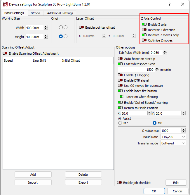
I have only tested the functionality with LightBurn so far, so this guide is only for this for the moment. I am happy to accept additions for LaserGRBL. First, the z-axis must be activated. In addition, I recommend activating the check mark for “only relative z-movements”, which makes it much easier to use later after the height adjustment.
This will give you two new arrows in the Move window, as well as in the layer settings:
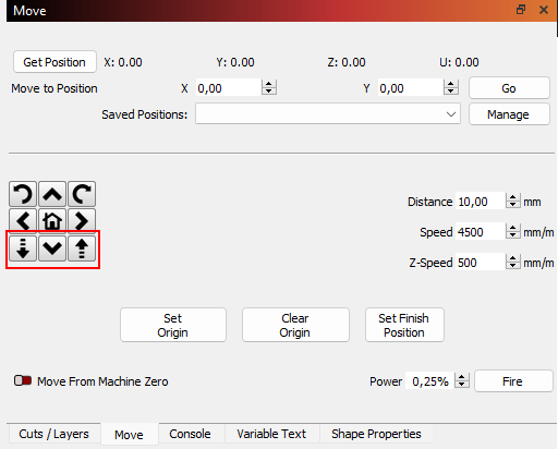
With these buttons, the head can now be moved up and down (and at this moment you can also test and adjust the parameters as described above).
Automatic focusing
This is probably the most interesting feature that is now possible (besides the new functions in the layer). This is not quite possible out-of-the-box, but is basically not difficult. I found it easiest to create a macro for this in LightBurn. Finally, it’s just a click then.
The core of the whole thing is the command G38 (probing) in grbl or g-code (explanation see here). With the command, the z-axis moves up to the workpiece until the probe switch triggers and then stops. There are several options, I prefer G38.3 because it does not throw an error if it fails and does not put the firmware into alarm mode. The command I use finally is:
G38.3 Z-63 F200G38.3 is the tool length measurement command. Z-63 indicates that from the current position (should be 0 after homing) 63 mm should be searched downwards. 63 mm is the longest my z-axis allows. F200 indicates the speed in mm/min. The last two parameters have to be adapted to your environment.
Thereafter, you know where the workpiece is. However, you should have mounted the switch in such a way that you have moved a little lower than the actual focus point of the laser. If you were to start like this now, the switch would constantly scratch the workpiece. Therefore, you should add some distance to drive back a little. In my case, the switch is (almost randomly) mounted in such a way that it triggers at a focus distance of 17.2 mm. This means that the head must then be moved back up 2.8 mm to reach the distance of 20 mm. This is possible with the command:
G91 G1 Z2.8 F200Here, G91 sets the subsequent movement in relative coordinates, i.e. from the current point. G1 specifies a linear motion performed with Z2.8 2.8 mm in the z-direction, with the speed F200 = 200 mm/min. I have saved these two commands in a macro where they are executed directly one after the other. To do this, you can right-click on one of the macro keys in LightBurn to create and name a new macro.
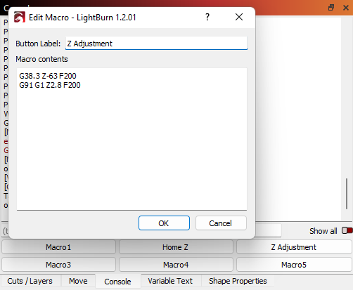
As can be seen in the screenshot, I have also created a macro for homing the z-axis, which only contains the line “$HZ”. This could also be transferred to the other macro, then you have ensured that the head is at the top before focusing.
Automatic readjustment per layer
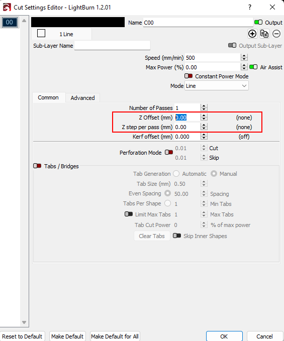
As illustrated by the LightBurn screenshot above, you now also have two new options in the layer settings. “Z Offset” and “Z Step per Pass”. The explanation can be found in the LightBurn documentation. You can either set a focus offset for the entire project, or adjust the depth for several passes for each pass. This is interesting with thick materials, where you can, for example, go 0.5 or 1 mm deeper each pass to always have the focus optimally on the cutting depth. In my opinion, it is particularly important here that “Relative Z Moves” is activated in the device settings. Otherwise, you quickly get unwanted z-movements.
Result
Here are two videos that show the homing and focusing.
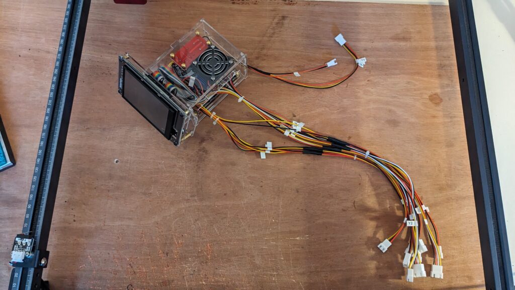
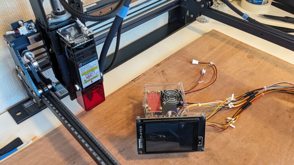
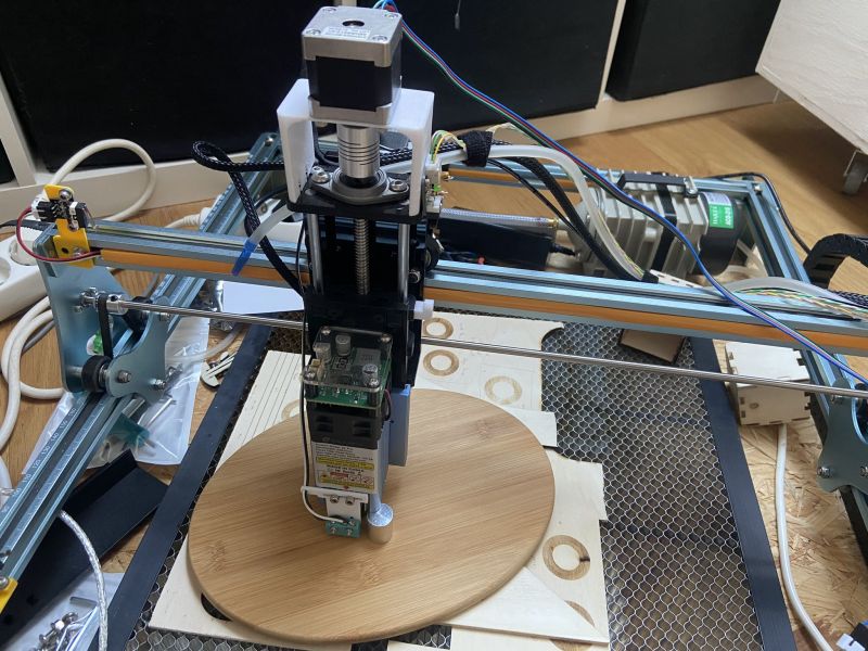
Gallery
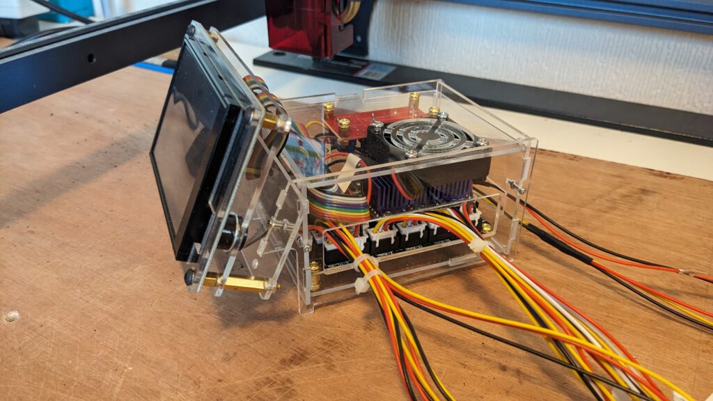
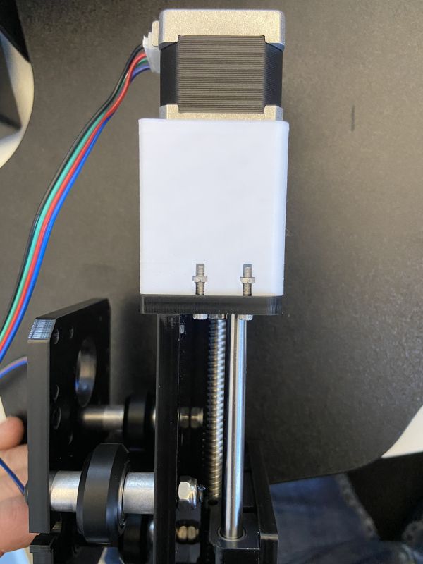
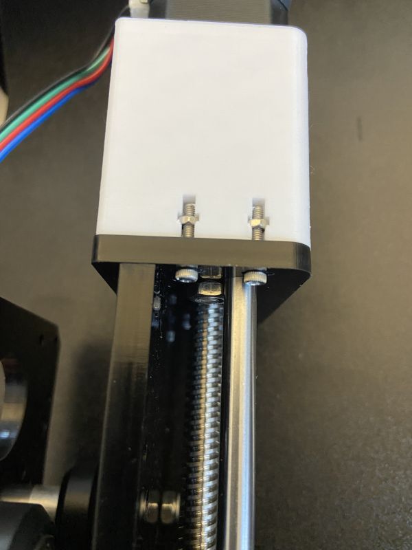
Here are a few pictures of the different expansion and construction stages, for a better understanding.

Here is another design by John, who adopted the z-axis adjustment for the S30 series. You can download the mounting plate here.