Adding relay to control extra devices
Most control boards offer the ability to attach a relay that can be triggered by firmware commands. You can use this, e.g., for controlling the air assist compressor. If the firmware is compiled with standard parameters (or taken from LaserGRBL), there is one control command available. This command is “M8”. This is a G-code command as explained in the Basic Principles chapter. There is another command, “M7”, that is available only if you compiled your firmware and activated this function. Both commands tell the firmware to trigger a pin on the control board which can be used to control other devices like lights, fans, or air assist systems. To turn off the pins, issue the “M9” command in the command line. Both pins are turned off, you can’t turn off them individually. The following picture shows where you find the pins that are controlled by those commands.

Since those pins are incapable of driving high loads, you need to connect a relay to them. The picture shows how to do it. There is a pin header in the top right of the board next to the end stop connectors. Here you find some analog microcontroller pins made available. The ones we are looking for are A3 and A4 (this one only if you use your individual firmware as mentioned above). Most relays need three pins to be controlled: VCC and GND (voltage) and the control signal (sometimes named IN, or S). Connect them as depicted, and you are ready to go. Now you can test it by typing “M8” in the command line and pressing the enter key. You should hear a clicking sound at the relay (or a small LED showing status). If you used a solid-state relay, there is no clicking sound. For solid-state relays, I recommend one that has separate inputs for voltage and trigger, like this one: AliExpress.
Due to the characteristics of the relays, I recommend using SSRs. Those also can help if you have issues with electrical interference caused by the switching relay. Here is some explanation from Mitch (FluidNC):
“To explain the theory of why the SSR module worked, but the conventional relay did not: When you turn a conventional relay on or off, it usually causes interference in the AC mains as the load device instantly starts to draw current or stops drawing current. This does not happen with SSRs because they have special “zero-voltage turn-on, zero-current turn-off” circuitry. That circuitry waits until the AC waveform is switching polarity, at a very low instantaneous voltage, before it connects the load, so the load current ramps up instead of going to its full value immediately. A similar thing happens at turn-off, waiting until the load current is nearly zero before disconnecting. The interference from the conventional relay often leaks into other electronics, potentially causing microprocessors to reset, or causing transmission errors on USB connections.”


If you use a conventional relay, I recommend buying one that can select between high-level-active and low-level-active, like this: Amazon-Link. This way, you can invert the logic at the relay. Some users had the relay active all the time and only turned off if they commanded M8. In this case, you need to invert the relay logic from high-level to low-level or vice versa. The standard trigger is defined in the firmware like this: low-level: disabled/high-level: enabled (the relay should state high-level-active in this case). You can also compile your own firmware to invert this setting, in case you have a low-level-active relay that can’t swap input logic. Another remark: make sure, the relay is rated for 5V (not 12V or something different). The power line needs to connected to the COM and NO (normally open) contacts on the high voltage side.
Warning
Using a relay, you can connect/control any load to it. Even 110/220V devices like the air assist compressor. Only do that by yourself, if you know what you are doing! Electricity is nothing to play with, it can be deadly! Better ask an electrician to help you out.
The control board itself is harmless to work with, it only contains 5V and 12V power lines which can safely be touched while active (though it might break if you cause a short circuit). Hence, you better disconnect it from power (power supply AND USB cable) while connecting cables.

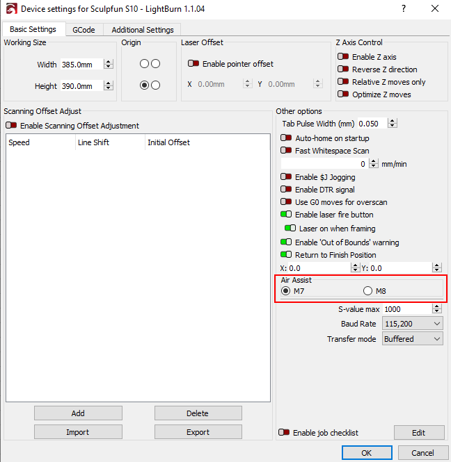
Configuring LightBurn to automatically turn on / off air assist
LightBurn can be configured to automatically use those commands to start / stop the air assist compressor while working.


From now on, the compressor is turned on while the laser is working and turned off afterwards.

Sculpfun S10
With the S10, there is a small change to the S6/S9 (at least with the current version of the firmware). The ports are named differently, and as far as I found out, there is only one pin that can be toggled. The pin is IO04 and is toggled by the M7 command.
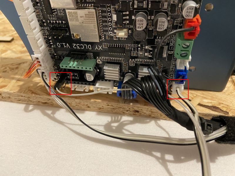
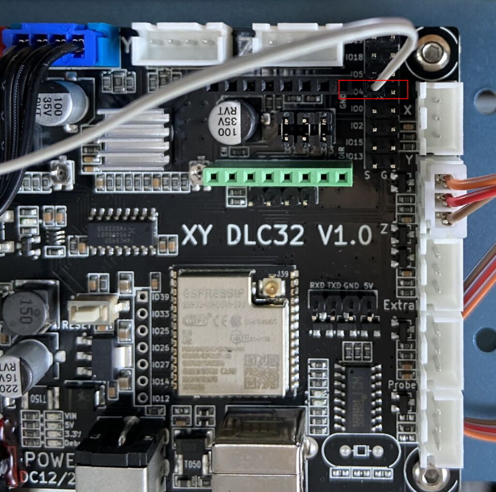
To control the relay, you have to use the command M7, not as usual M8 (I think with further firmware versions this will also be improved / changed). It is also important that it is a high-level trigger relay, as you can not invert the pin here. For example: AliExpress link
Sculpfun S30
Normally, you don’t need a relay anymore with the S30 series of Sculpfun lasers because there is a relay / mosfet on the board, which directly supplies the included pump. In this case, the mainboard supplies all the power for the pump, the pump itself has no extra power connection anymore. Therefore, it is also important to note that S30-5W and S30-10W get a different pump supplied (12V) than the Pro Max with 20W and 24V. But if you don’t want to connect an original pump, but another pump / compressor, you can also connect a relay here. In this case, I recommend the types of relays that I had excluded above because here the power is available to also operate such relays. It looks then as follows:

MKS DLC32
If you use a MKS DLC32 mainboard, you can connect a relay as well, as shown in the diagram below (thanks to Lionel Koehl). More info can be found in the wiring manual of the DLC32 board.

The control of the relay is also done using the M7 command.
Additional I/O pins
Outputs
Most mainboards offer additional pins that can be switched by software. With 8Bit boards, however, it is mandatory to go relatively deep into the source code to make them usable. Using 32Bit boards, it is a bit easier by using the FluidNC firmware. With this, for example, six additional pins can be used on the S30 mainboard to control arbitrary functions. For the S10 and MKS-DLC32 boards this is the same, only the pin names have to be adapted. Here I explain it for the S30 mainboard. On the mainboard, there is a slot with six I/O pins. To be able to use them, they have to be added in the configuration of FluidNC (however, I could only control a maximum of four pins at a time, this could be a bug in Fluid). Further hints for the installation and the finished config file of FluidNC can be found on the firmware page. As usual with ESP32-based boards, the pins use 3.3V voltage, so be sure to use a relay that activates at 3.3V already (though most 5V relays should usually work).


Here is the documentation from the Fluid Wiki: http://wiki.fluidnc.com/en/config/user_outputs. If you have uploaded the configuration to FluidNC accordingly, you can now switch on the ports with the commands M62 P0 or M64 P0, and switch them off with M63 P0 or M65 P0. The difference between the two commands is described here: https://www.linuxcnc.org/docs/html/gcode/m-code.html#mcode:m62-m65. Now you can connect a relay to these pins again and control e.g., the lighting or the smoke outlet with it. For this, you can also insert the corresponding commands in LightBurn as start/end gcode to do this automatically, see picture above.
Inputs
The pins mentioned above can also be used as inputs, e.g. to connect additional switches to the laser and thus trigger actions, for example. FluidNC offers the possibility to link an input pin with a macro, which can contain any code to control the laser or to execute other actions.


Above, you can see an example how four switches (more is not possible) are connected to four of the pins of the mainboard. In Fluid, macros are defined to move the laser 10 mm at a time in the X or Y direction, so you could make a control pad out of it. Or you could use it to manually move the z-axis or trigger a homing or probing cycle. You can also use it to control one of the other I/O pins and control the lighting, for example.